I Built a Press Drill from 3D Printer Spare Parts
I needed to drill accurately across different materials. So I looked at the pile of spare parts from old printer builds and decided to build a press drill instead of buying one.

I needed a way to drill accurately - wood, acrylic, plastic, aluminum, and center-punching steel. A hand drill wobbles too much for precise work. And I wanted something portable and cordless - store-bought drill presses are bulky, stationary, and almost always corded.
Since portability was the goal, the frame had to be rigid enough to stand on its own - detachable base plate, usable both on the table and clamped directly onto a workpiece on-site.
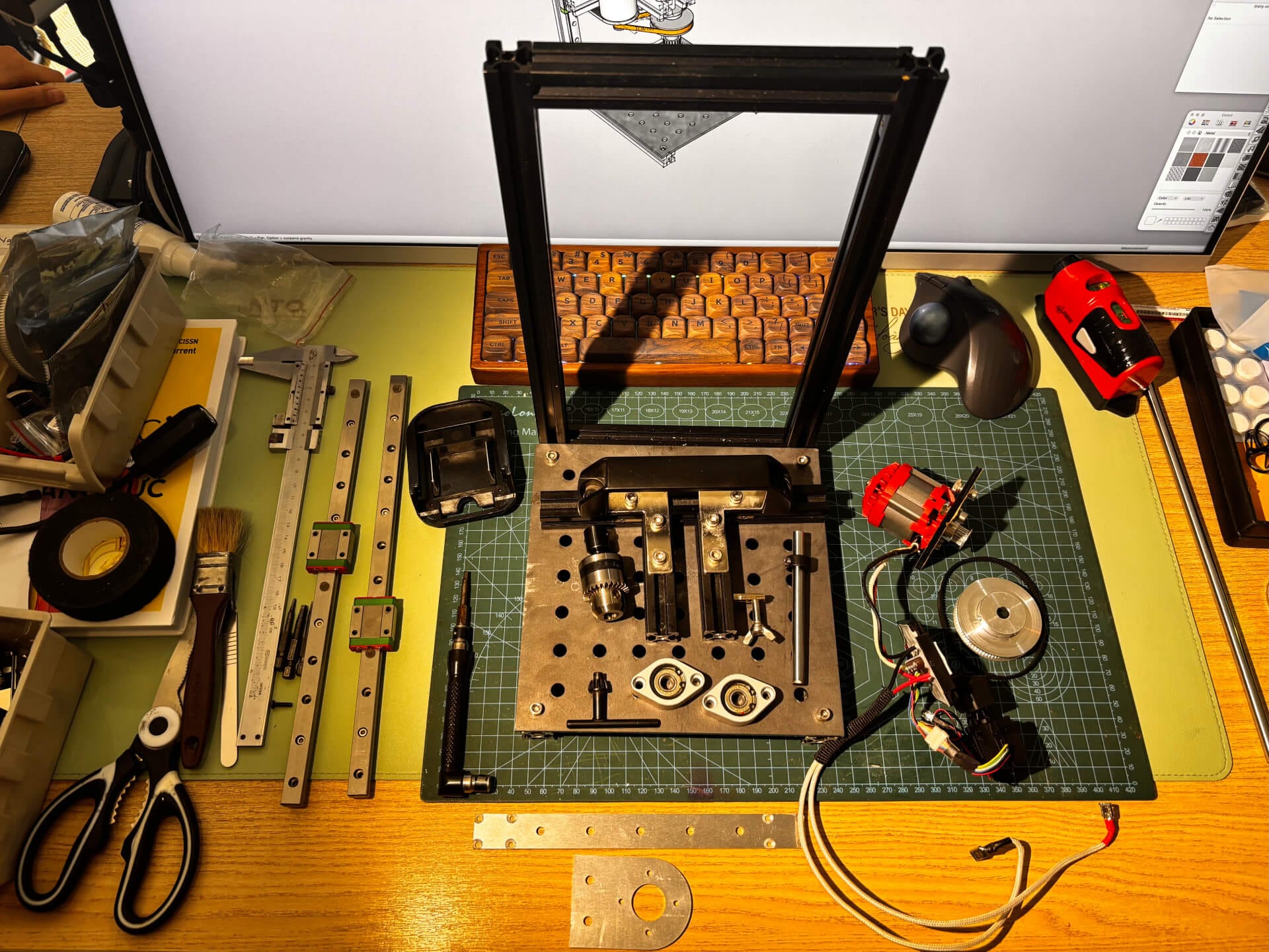
My approach when starting a build like this: go through the stock first, see what's usable, then design around what's there. Most of what I needed was already in the bin - leftover from past 3D printer projects. GT2 pulleys and belt, 8mm shaft, KFL08 pillow bearings, MGN12 linear rails, aluminum extrusion. For the motor, driver, and trigger, I bought a used hand drill and pulled the parts out. Power runs on an M21 battery - no cord needed.
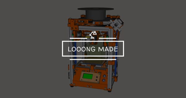
The design followed from that: a frame from aluminum extrusion, spindle assembly on the MGN12 rail, brushless motor driving the chuck through a GT2 belt reduction.
The Spindle Assembly
This was the part that took the most time to get right.
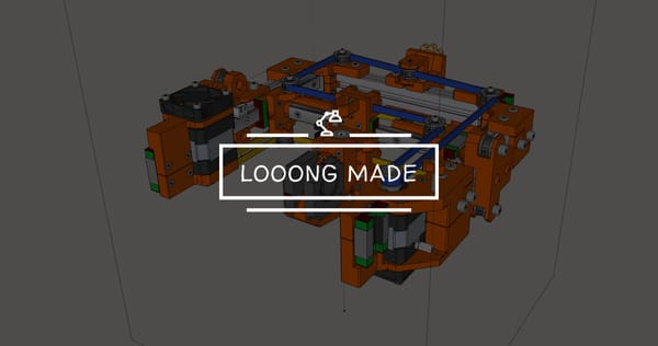
The brushless motor runs at 16,000 rpm - correct spec for a hand drill, but hand drills always come with a gearbox to bring that down. I stripped the motor out and dropped the gearbox - it added height I didn't want in the spindle. The solution was a belt drive: a 20T to 80T pulley ratio brings it down to 4,000 rpm, and moves the motor off to the side instead of sitting directly above the chuck. Smaller spindle height, better layout.
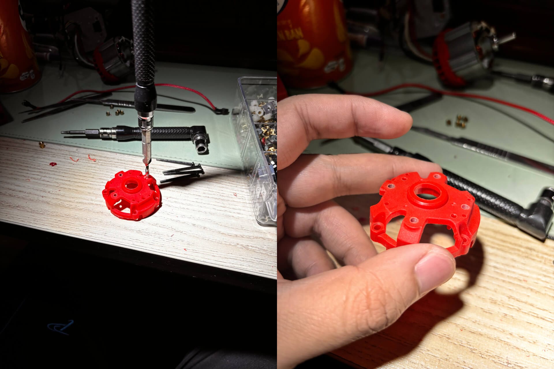
The motor housing had no mounting holes - just a bare cylinder. I had to tap threads directly into it to have something to bolt onto.
I started with an acrylic sheet for the motor mount - quick to cut, easy to work with. The bearing was a standard KFL08, which comes with self-alignment built in.
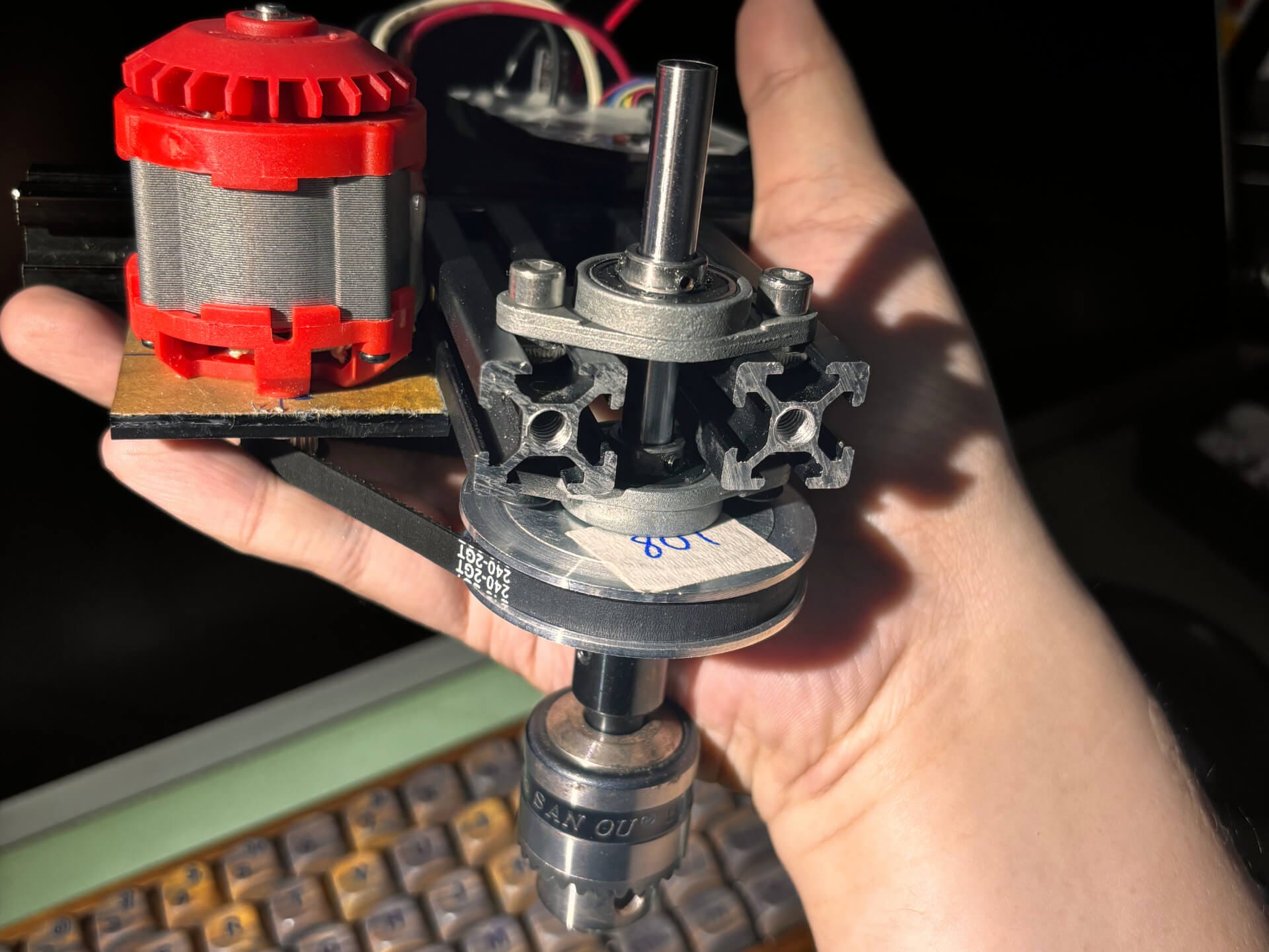
The belt reduction - brushless motor on the left, large driven pulley on the spindle shaft.
Once the machine was running, I could feel it wasn't precise enough. The self-aligning bearing was doing too much adjusting on its own. I switched to a non-standard KFL08 without self-alignment - these are hard to find. I tracked down one seller on Shopee shipping from China. The difference showed up immediately: shaft play dropped noticeably, something I could feel by hand. Before the swap, the chuck visibly wobbled at no load. After, it ran true. The holes came out cleaner too - no more oversized entry from the bit moving around.
What I Changed
The acrylic parts were never meant to be permanent. They were just cheap and fast to cut - good enough to check that everything fit and assembled without issues. Once the machine was running, I ordered the aluminum plates CNC-cut to the same dimensions and used the press drill itself to finish the countersinks.
There are two plates: the motor mount, and the Z gantry adapter - a piece that bridges the two MGN12C carriages and connects them to the 2020 extrusion carrying the spindle. The machine runs dual Z rails, so this adapter ties both sides together.
Going from 4mm acrylic to 3mm aluminum was a durability improvement, not a precision one - the acrylic was fine functionally. The KFL08 swap mattered more.
For the aluminum plates, I first tried doing it by hand - printed the CAD drawing, taped it onto aluminum flat bar, and drilled to the markings. It works, and it's a valid option for anyone building this.
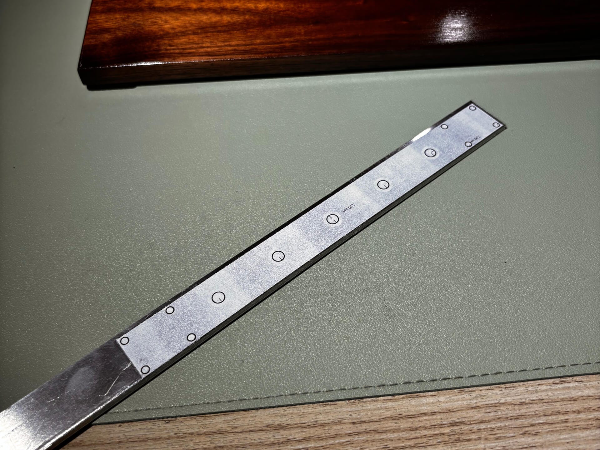
But CNC machining in Vietnam is cheap enough that I ordered both plates CNC-cut for the final version anyway.
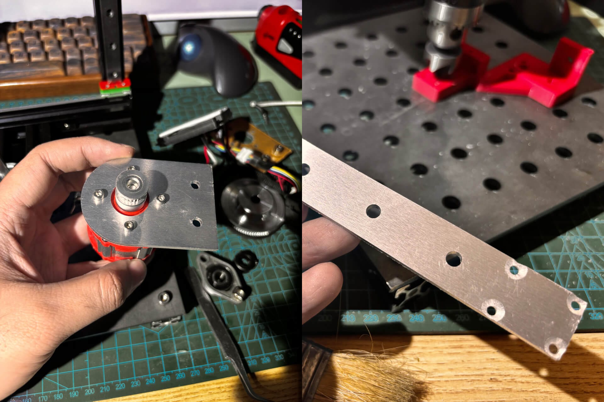
The frame itself was straightforward. Aluminum extrusion goes together quickly when you've done it a few times.
Z axis travel test after fitting the CNC-cut gantry adapter plate. MGN12 dual rail, no spindle mounted yet.
Putting It Together
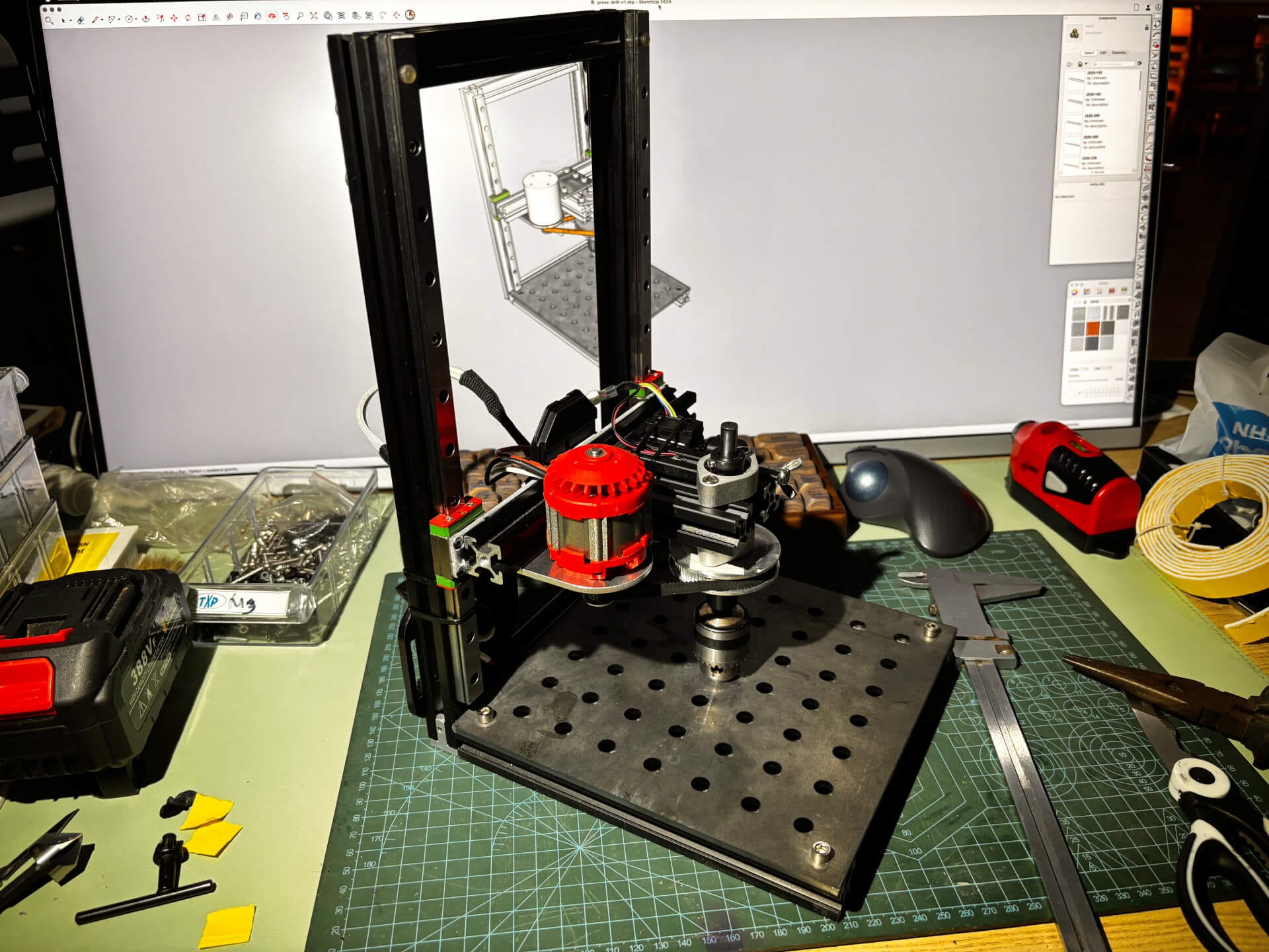
The physical machine ended up close to the SketchUp model. A few geometry adjustments along the way, nothing that needed a redesign.
I also added a lever for operating the Z axis - makes it easier to bring the drill down and back up with one hand while holding the workpiece.
Z axis operated by lever - brings the drill down and back up with one hand.
Parts List
- 2020 Aluminum Extrusion - Frame
- MGN12 Linear Rail - Z-axis
- GT2 Timing Belt - Drive
- GT2 Pulley 20T - Motor side
- GT2 Pulley 80T - Spindle side, 1:4 reduction
- 8mm Shaft - Spindle shaft
- KFL08 Pillow Bearing - 2x, non-standard without self-alignment
- Drill Chuck
- Brushless motor + driver + trigger - From a used hand drill
- M21 battery
The motor mount plate and Z gantry adapter plate can be made by hand - print the CAD drawing, tape it onto aluminum flat bar, and drill to the markings. I tried that first. In the end I ordered them CNC-cut anyway, since CNC machining in Vietnam is cheap and the accuracy is worth it.